Source Values
Devices
Mouse
The Mouse node provides the current x and y coordinates of the mouse in the view plane (screen space) within the Scene Viewer. Both values are in the range 0-1.
To compare 3D positions with view plane coordinates, use the View Plane Position node.
Keyboard
The Keyboard node monitors the keyboard for a particular key press. It matches the current key against the input value (as an ASCII value). When it matches, it returns 1; otherwise 0.
Texture
Texture Value
The Texture Value node returns the RGBA value from the texture at position uv. To see how you can map 3D coordinates to 2D UV values, see Texture Mapping.
Texture Value LOD
Use the Texture Value LOD node to avoid texture edge artifacts when, e.g., wrapping a texture around spheres or applying an equirectangular mapping to a cube.
Start with the Texture Value node for regular texturing. Switch to Texture Value LOD when you see seams or artifacts at texture boundaries, or moiré patterns or aliasing.
Texture Value LOD Zero
The Texture Value LOD Zero is used to extract texture values in vertex (deformation) shaders.
Feedback Depth Value
The Feedback Depth Value node returns the raw depth and linear depth values from the output of the previous frame at view plane position uv. You can use View Plane Position to derive the current (or other) position in view plane coordinates. The linear calculation uses current camera near and far clipping plane values, but these can be overridden. The linear value is normalized to 0.0 - 1.0. Calculation: linear = (2.0 * near * far) / (far + near - ((raw * 2)-1) * (far - near)), normalized with (linear - near)/(far - near).
Sound
Frequency Volume
The Frequency Volume node looks at incoming sound data (from a Microphone or Audio Track node), and turns it into a floating point value that can be used in other nodes.
When you click on the node, you can select which frequencies you want it to listen on:
- Overall
- Low Frequencies
- Mid Frequencies
- High Frequencies
The audio spectrum is converted into logarithmic frequency bands that match human hearing perception, and for each A-weighting is applied to compensate for how humans naturally perceive different frequencies (i.e. adjusting for how our ears are less sensitive to very low and very high pitches).
Frequency Split 5
The Frequency Split 5 node makes it easy to pick up the intensity in any of the frequency bands based on audio data (from a Microphone or Audio Track node).
The audio spectrum is converted into logarithmic frequency bands that match human hearing perception, and for each band A-weighting is applied to compensate for how humans naturally perceive different frequencies (i.e. adjusting for how our ears are less sensitive to very low and very high pitches).
Frequency Split 10
The Frequency Split 10 node further subdivides the frequency bands based on audio data (from a Microphone or Audio Track node).
The audio spectrum is converted into logarithmic frequency bands that match human hearing perception, and for each band A-weighting is applied to compensate for how humans naturally perceive different frequencies (i.e. adjusting for how our ears are less sensitive to very low and very high pitches).
Frequency Split 256
The *Frequency Split 256 node divides the frequency bands based on audio data (from a Microphone or Audio Track node).
The audio spectrum is linearly divided into 256 segments, and for each segment A-weighting is applied to compensate for how humans naturally perceive different frequencies (i.e. adjusting for how our ears are less sensitive to very low and very high pitches).
Gestures
Hand Gesture
The Hand Gesture node captures a particular gesture from a hand based on texture input (usually video from the camera).
These gesture property accepts the following values:
- None
- Closed Fist
- Open Palm
- Pointing Up
- Thumb Down
- Thumb Up
- Victory
- I Love You
The hand property determines if it’s the first or second hand present in the video stream. If only one hand is present, it should be set to 0.
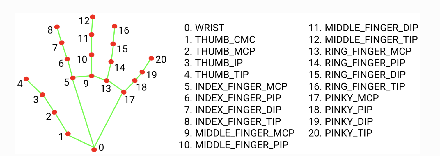
Gesture Landmark 2D
The Gesture Landmark 2D node captures the 2D view plane (screen space) coordinates of a specific gesture landmark from a hand based on the gestureData input provided by the Gesture Data node.
To compare 3D positions with view plane coordinates, use the View Plane Position node.
Gesture Landmark 3D
The Gesture Landmark 3D node captures a specific gesture landmark from a hand based on the gestureData input provided by the Gesture Data node. It’s similar to Gesture Landmark 2D, but also provides depth (z-coordinate). NB. The value of the z-coordinate is small, as is the depth relative to the wrist landmark.
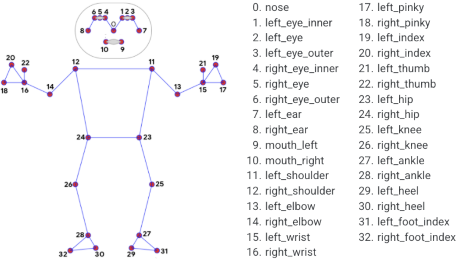
Pose Landmark 2D
The Pose Landmark 2D node captures the 2D view plane (screen space) coordinates of a specific pose landmark from a figure based on the poseData input provided by the Pose Data node.
To compare 3D positions with view plane coordinates, use the View Plane Position node.
Mapping
Planar Mapping XY
Maps 3D coordinates to a 2D surface in one plane only, either XY (front/back), XZ (top/bottom), or ZY (left/right).
The example below shows planar mapping in the XY plane.
Box with image in XY plane (front/back) side only.
(source)Planar mapping does not flip the back image, so when viewed from the back, it will appear mirrored.
Planar Mapping XZ
Maps 3D coordinates to a 2D surface in one direction, either XY (front/back), XZ (top/bottom), or ZY (left/right). For more information see Planar Mapping XY.
Planar Mapping ZY
Maps 3D coordinates to a 2D surface in one direction, either XY (front/back), XZ (top/bottom), or ZY (left/right). For more information see Planar Mapping XY.
Box Mapping
Maps a texture onto all six sides of a box. Orients all textures outwards, so that no side is mirrored, e.g., a text in the texture can be read on all sides.
Box with image mapped onto all six sides of the cube.
(source)Spherical Mapping
Maps a texture onto a sphere. As the texture wraps around, it is best to use Texture Value LOD to avoid artifacts at the seam.
If you map an equirectangular image using this method, it will seamlessly wrap around the sphere (as if the sphere reflected the surroundings).
Sphere with an equirectangular images mapped onto it.
(source)Cylindrical Mapping
Maps a texture onto a cylinder (in the Y direction).
Cylinder with an images mapped onto it.
(source)View Plane Mapping
Maps an image in the view plane (i.e. the screen plane). This means the 3D properties of the object becomes irrelevant.
Image mapped into box in the view plane.
(source)Box Atlas Mapping
The Box Atlas Mapping is used to map six different images onto the six sides of a cube. The six images must be part of a composite atlas image containing 2x3 smaller images (see below).
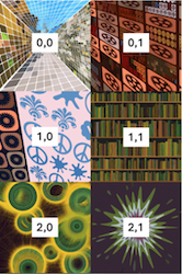
Box with an atlas image mapped onto all six sides of the cube.
(source)Equirectangular Mapping
The Equirectangular Mapping node is used to map an Equirectangular Image onto a cube.
If the cube is seen from inside, it creates a seamless 360-degree background, just as when Equirectangular Images are used for the overall scene Background.
nodeake sure to set Material Sides to Back or Both, and disable shadows.
Box with an equirectangular image mapped onto its inside
(source)Stretched Mapping
The Stretched Mapping node creates a UV mapping in the XY plane that wraps around the edge, taking into account the Z-coordinate to a degree determined by the zFactor parameter.
The example below shows Stretched Mapping with a zFactor of 0.5.
*Stretched Mapping with zFactor of 0.5.
(source)Box Map Index
The Box Map Index node returns the index of the side of a box to which the 3D coordinates would be mapped. This should be used together with the RGBA Selector nodes to map different RGBA streams to the different sides of a cube. If you want to map different images to the different sides, make sure to use Box Mapping for the uv input to Texture Value .
Different images mapped to each side using Box Map Index.
(source)