Particles
Create a particle cloud that moves
In this project you’ll create a cloud of 100,000 particles that first change according to noise functions and gestures.
Create particles cloud and adjust particle sizes
- First create a new scene by clicking the button in the pop-out menu (save your previous project first with ).
- Use the Add … drop-down to add a Sphere Particles object.
- By default the object includes 1,000 particles. Change the parameters section from [2, 2, 2, 1000] to [2, 2, 2, 100000] to create 100,000 particles.
- If you zoom in, you can see the individual particles. Note that the particles have the same size, regardless of how close or far away your are. This means that the particle cloud almost looks solid when looking at it from far away.
- Double-click the particle cloud to open the Shader Editor.
- Add a →Point Size node (from the VERTEX OUT section).
- Add a Camera Distance node (from the ENVIRONMENT section).
- Add a f(x)→Float expression (from the MATH section).
- Double click the node and change the expression to 0.4 / pow(x*0.2 + 0.1, 2).
- Connect the Camera Distance node to the input of the f(x)→Float node, and connect the output of the f(x)→Float node to the input of the →Point Size.
- When you zoom in you will now see how the particles closest to the camera are larger than the particles further away (this is best seen if the cloud object is deselected, as selecting it amplifies the particle size).
Particle cloud with particle size changing according to camera distance.
(source)Set particle colors
- We will set the particle colors based on distance from the center.
- Add a H•S•L•A→RGBA node (from the HSLA section).
- Add a Distance to Position node (from the 3D OPERATIONS section).
- Add a 3D Position node (from the ENVIRONMENT section).
- Connect the 3D Position xyz output to the position input of the Distance to Position node.
- Connect the distance output to the h input of the H•S•L•A→RGBA node.
- Connect the rgba output to the rgba input of the →RGBA Output node.
- Look around, zoom in, and you can see how the colors change with distance from the center point.
Particle cloud with particles colored according to distance from center.
(source)Create a wave
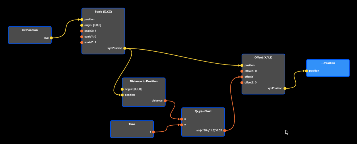
-
Add another 3D Position node (from (from the ENVIRONMENT section).
-
Add a Scale (X,Y,Z) node from (from the 3D OPERATIONS section).
-
Add a →Position node (from the VERTEX OUT section).
-
Connect the xyz output of the 3D Position node to the position input of the Scale (X,Y,Z) node.
-
Connect the xyzPosition output to position input of the →Position node. Nothing should have changed. We should still have a colorful sphere.
-
Double click the the Scale (X,Y,Z) node and set scaleY to 0. This should collapse the sphere into a flat “pancake”.
-
Add a Time node (from ENVIRONMENT section), and a Distance to Position node (from the 3D OPERATIONS section).
-
Add a f(x,y)→Float node (from the MATH section).
-
Connect the t output from Time to y input of the f(x,y)→Float node.
-
Connect the xyzPosition output of the Scale (X,Y,Z) node to the position input of the Distance to Position node. Note that the Scale (X,Y,Z) output is connected to two different nodes. Outputs can always be connected to multiple nodes.
-
Connect the distance output to the x input of the f(x,y)→Float node.
-
Double click the node and set the expression to sin(x*30-y*1.5)*0.02.
-
Add a Offset (X,Y,Z) node (from the 3D OPERATIONS section).
-
Insert the Offset (X,Y,Z) node between the Scale (X,Y,Z) node and the →Position node by connected the former’s xyzOutput to the position input of the Offset (X,Y,Z) node, and the xyzPosition output of this node to the position input of the →Position node.
-
Lastly, connect the output of the f(x,y)→Float node to the offsetY input of the Offset (X,Y,Z) node.
-
You will now have a drop wave particle cloud.
A particle cloud with a wave.
(source)Deform shape with index finger tip
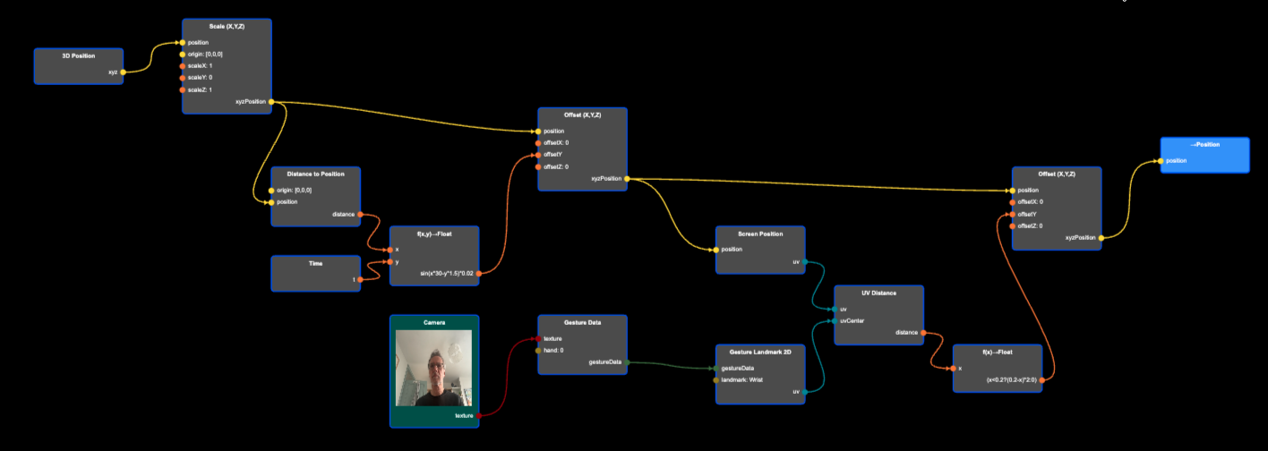
-
As before, to recognize a gesture we need to add a Camera node, a Gesture Data node, and a Gesture Landmark 2D node. These nodes will give us the position of the gesture landmark. You could set it to index finger tip, but any landmark will do.
-
Connect the Camera texture output to the texture input of the Gesture Data node, then connect the gestureData output of the Gesture Data node to the gestureData input of the Gesture Landmark 2D node.
-
Now add a Screen Position node (from the ENVIRONMENT section), and connect the xyzPosition output from the Offset (X,Y,Z) node to the position input of the Screen Position node. This will map the 3D position in the scene to its position on the screen.
-
Add a UV Distance node (from the UV Operations section).
-
Connect the Screen Position output to uv input of UV Distance, and connect uv output from Gesture Landmark 2D to the uvCenter input of the UV Distance node. This node calculates the distance between a particle and our gesture landmark (e.g. index finger tip) on the screen. We will use this distance to deform the wave.
-
We need to add two more nodes: One more Offset (X,Y,Z) node (from the 3D OPERATIONS section), and a f(x)→Float node (from the MATH section).
-
Connect the distance output from the UV Distance node to the x input of the f(x)→Float node.
-
Double click the f(x)→Float node, and set the expression to (x<0.2?(0.2-x)*2:0). In other words, if the distance between the particle and the finger tip is larger than 0.2, we will output 0, and if it’s smaller than 0.2, we will output (0.2-x)*2.
-
Now insert the new Offset (X,Y,Z) node in between the old Offset (X,Y,Z) node and the →Output node by connecting the xyzPosition of the old Offset (X,Y,Z) to the position input of the new Offset (X,Y,Z), and the xyzOutput of the new node to the the position input of the →Position node.
-
Then connect the output of the f(x)→Float node to the offsetY input of the new Offset (X,Y,Z) node.
-
As you move your finger across the screen, it should modify the shape of the wave. Make sure you have enabled the camera.
Completed Project
A wave that can be modified with a finger tip.
(source)