Shapes
Interactively modify the shape of a 3D object
In this project you will enable users to interactively modify the geometry (shape) of an object, rather than its material (surface).
An objects shape is determined by its vertices, and the triangular faces between them that create its surface. You can see this for the sphere by clicking the Wireframe button in the object properties section of the pop-out menu.
Interactive Size Changes
Instead of modifying surface colors, we will modify the shape of an object.
- Start by hiding the box by unchecking it in the list under 3D Objects in the pop-out menu.
- Then add a Sphere using the Add… drop-down.
- Copy the material from the box to the sphere using the Copy from… drop-down.
- You now have an interactive sphere, with the same interactive material as the box.
- You will now modify the node code to affect the shape of the sphere, rather than the surface colors.
- Open the Shader Editor by double clicking the sphere in the Scene Viewer.
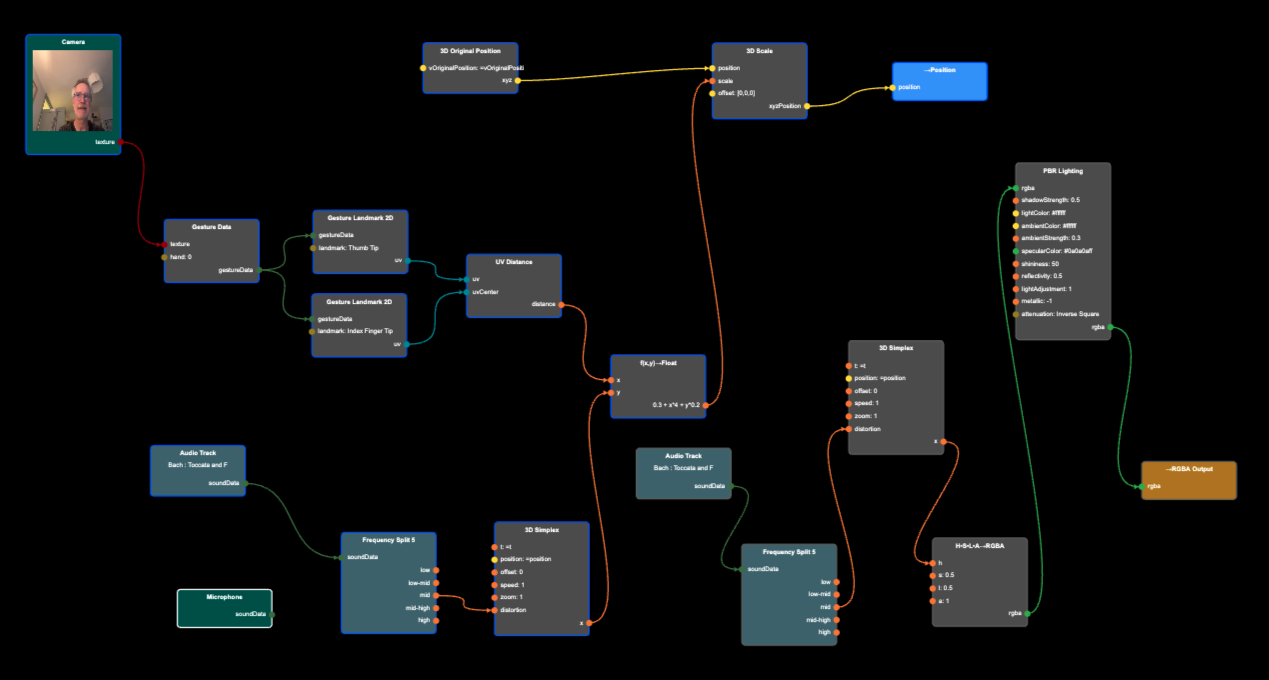
- Add a 3D Original Position node (from the ENVIRONMENT section) - the original position of the vertex. Add a →Position node (from the VERTEX OUT section) - the position we want it to have. We will use our interactive data to move the original position and assign it to the output position.
Please note that you can not connect nodes related to the material (surface) with nodes related to the geometry (shape). The two networks cannot be connected. - To avoid interconnecting the vertex network (related to the geometry), with the fragment network (related to the material), disconnect the UV Distance distance output from the Texture Scale scale input. The default scale value of 1 will take effect, scaling the camera input to cover the whole sphere.
Your sphere should now look something like this. - Add a 3D Scale node (from the 3D OPERATIONS section), and connect its position input to the 3D Original Position xyz output, and connect its xyzPosition output the →Position input. Nothing should change, as we’re scaling the sphere by 1.
- Double click the 3D Scale node, and change the scale value to 0.5, and to 1.5, and you can see how the size of the sphere changes.
- Connect the distance output from the UV Distance node to the scale input of the 3D Scale scale input.
- You should now be able to control the size of the sphere using your thumb and index finger. Make sure the camera is enabled.
Control the size of the sphere with your thumb and index finger.
(source)Strong irregular deformations based on noise
- Let’s remove the camera image from the sphere. Delete Texture Value, Texture Scale, and Box Mapping nodes.
- Also remove the Alpha Blend and H•S•L•A→RGBA nodes.
- Disconnect the Frequency Split 5 node from the 3D Simplex node.
- If you want to control the color of the sphere, you might add a RGBA Color node and connect it to the rgba input of the PBR Lighting node.
- Add a x+y node, and connect its two inputs to the UV Distance output and the 3D Simplex output.
- Now connect it’s output to the 3D Scale input.
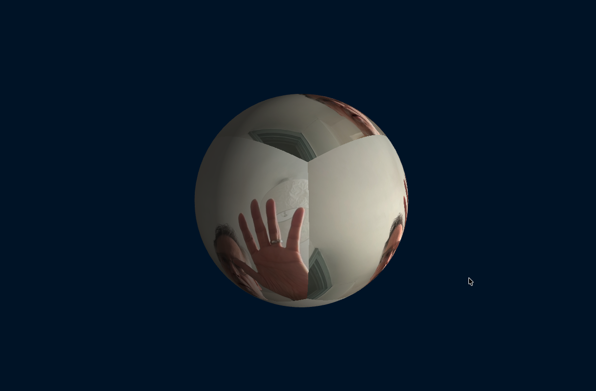
- You can see that the deformation is too strong. It’s completely breaking up the surface, and the finger control of size has become almost irrelevant.
Strong irregular size deformations based on 3D Simplex noise input
(source)Soft irregular deformations based on noise
- We soften the deformations by adding a f(x,y)→Float node (from the MATH section) for the calculation.
- Replicate the x+y node connections for the f(x,y)→Float node, then delete the x+y node.
- Double click f(x,y)→Float, and in expression field enter 0.3 + x + y*0.1.
- The soft noise deformations are now small enough that using the thumb and index finger you can noticeably change the size.
Soft irregular size deformations based on 3D Simplex noise input
(source)Soft irregular deformations based on noise and sound
- Connect Frequency Split 5 mid output with the distortion input of the 3D Simplex node.
- Double click the f(x,y)→Float node and change the expression to 0.3 + x + y (to make the sound and noise more prominent).
- You will now be able to control the overall size with your fingers, and the noise distortion with sound input.
Soft irregular size deformations based on 3D Simplex and sound
(source)Optional - Add music and colors
- Replace the Microphone input with a Audio Track.
- Adjust the strength in the f(x,y)→Float node appropriately.
- Since we cannot connect the vertex network (shape deformation) with the fragment network (surface colors), we will copy-paste the three nodes: Audio Track, Frequency Split 5, and 3D Simplex. Select them all by using the shift key, then command-C and command-V to copy paste.
- Add a H•S•L•A→RGBA node, and connect it’s h input with 3D Simplex output, and connect the H•S•L•A→RGBA output to the PBR Lighting rgba input.
- You might want to adjust values to increase the impact, e.g. change the expression to increase impact of thumb and index finger to something like: 0.3 + x*4 + y*0.2, and maybe add math nodes in other areas.
Completed Project
Soft irregular size deformations based on music
(source)Code